3 Phase Inverter Circuit Diagram Free Download

1 Three Phase Inverter Circuit Download Scientific Diagram

Three Phase Inverter Circuit Download Scientific Diagram

Three Phase Inverter Circuit Diagram Download Scientific Diagram

Circuit Diagram Of Three Phase Inverter With Transformer Download Scientific Diagram

Circuit Diagram Of A Three Phase Inverter With An Lc Output Filter For Download Scientific Diagram

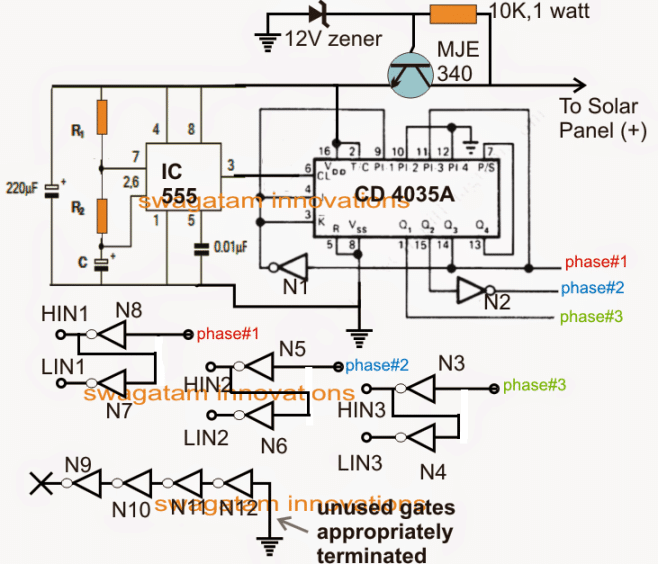
Electronic Circuit Projects Solar 3 Phase Inverter Circuit Circuit Projects Arduino Electronics Circuit

3 phase inverter circuit diagram free download rotary phase converter wiring diagram.
3 phase inverter circuit diagram free download.

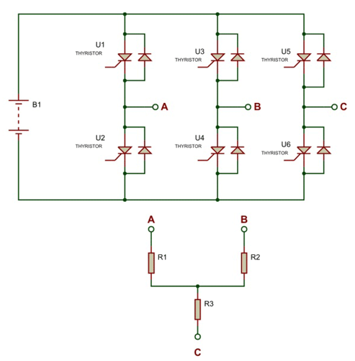
Circuit Diagram Of Three Phase Inverter And Load Download Scientific Diagram

Three Phase Inverter Circuit 120 Conduction Mode Each One Of The Six Download Scientific Diagram

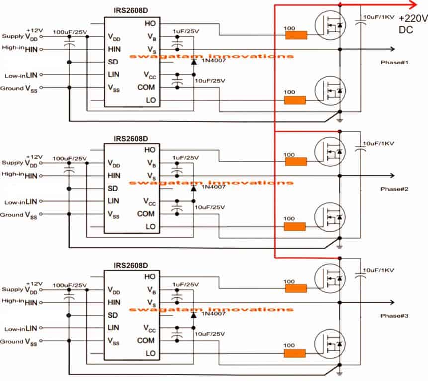
Simple Effective 3 Phase Inverter Circuit Circuit Projects Arduino Electronics Circuit

Make This 3 Phase Inverter Homemade Circuit Projects Circuit Projects Electronic Circuit Projects Circuit Diagram
Simple 3 Phase Inverter Circuit Homemade Circuit Projects

Three Level Single Phase Inverter Circuit Download Scientific Diagram
3 Phase Inverter Circuit Diagram Wiring Schematic 1964 Vw Fuse Box Jeep Wrangler Tukune Jeanjaures37 Fr

Simulation Circuit For A Three Phase Inverter Using Matlab Download Scientific Diagram

Arduino 3 Phase Inverter Circuit With Code Homemade Circuit Projects In 2020 Circuit Projects Arduino Electronics Circuit
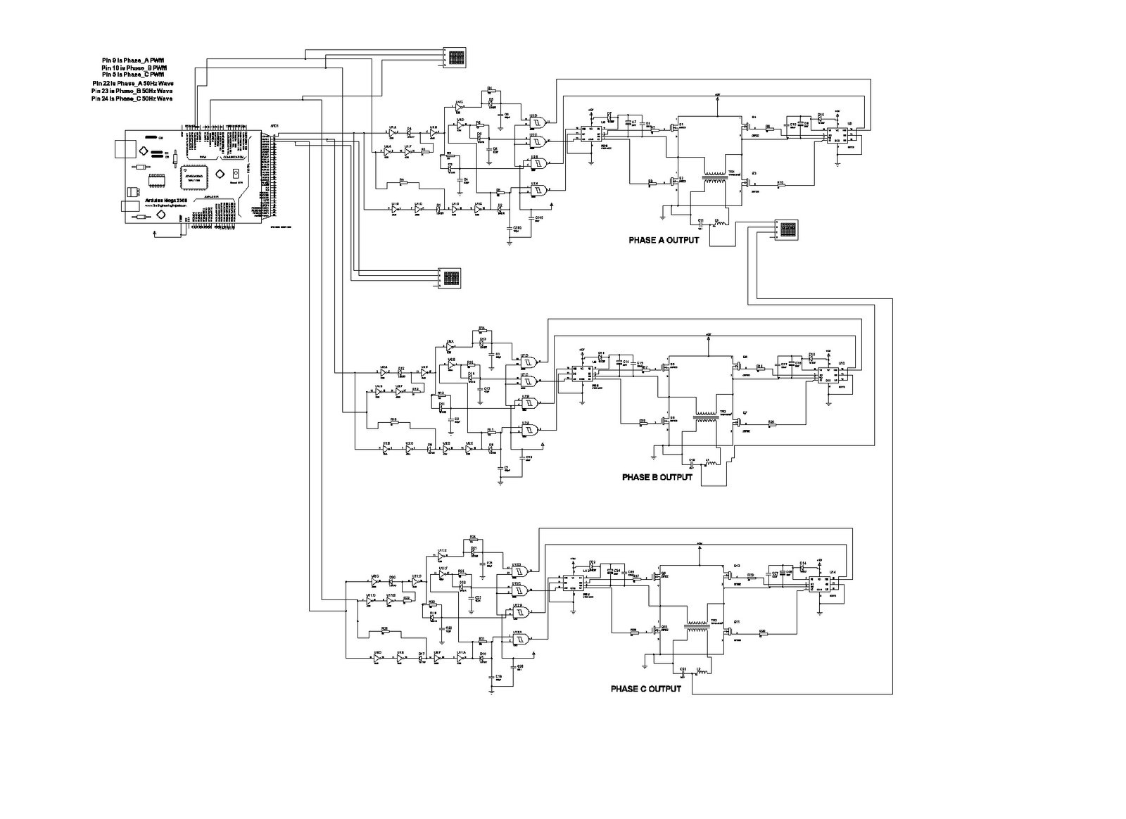
Three Phase Sine Wave Inverter Circuit Using Arduino

Three Phase Inverter And An Equivalent Circuit Of Bldc Motor Bldc Download Scientific Diagram

Power Circuit Of A Three Phase Voltage Source Inverter Vsi Download Scientific Diagram

Three Phase Inverter Circuit Circuit Diagram Centre Electronic Circuit Projects Circuit Diagram Circuit Projects

Three Phase Pmsm Inverter Circuit Download Scientific Diagram

Power Circuit And Control Schematic For The Three Phase Download Scientific Diagram

Three Phase Four Leg Inverter Download Scientific Diagram
Arduino 3 Phase Inverter Circuit With Code Homemade Circuit Projects

Flyback Boost Converter For Solar 3 Phase Inverter Teknik Listrik Teknik Listrik
Https Encrypted Tbn0 Gstatic Com Images Q Tbn And9gcqvv 3jt8dbimwdxsbdlsnuxofafgkwytvrhbtowqrdrimhgfam Usqp Cau
Three Phase Pwm Inverters With A R L Load Download Scientific Diagram

Electronic Circuit Projects Solar 3 Phase Inverter Circuit Electronic Circuit Projects Circuit Projects Electronics Circuit
Shows The Complete Circuit Diagram Of The Pwm Inverter Circuit Ic 3 Download Scientific Diagram

Arduino 3 Phase Inverter Circuit With Code Homemade Circuit Projects In 2020 Circuit Projects Arduino Electronics Circuit

Schematic Diagram Of Single Phase Full Bridge Inverter Circuit Download Scientific Diagram
Source : pinterest.com
