3 Cfl Ups Inverter Circuit Diagram
Draw Your Wiring 3 Cfl Ups Inverter Circuit Diagram
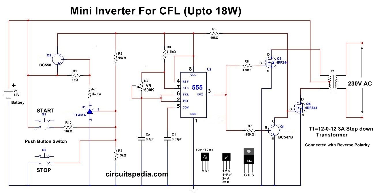
12v Cfl Inverter Circuit Simple Cfl Inverter Circuit Diagram
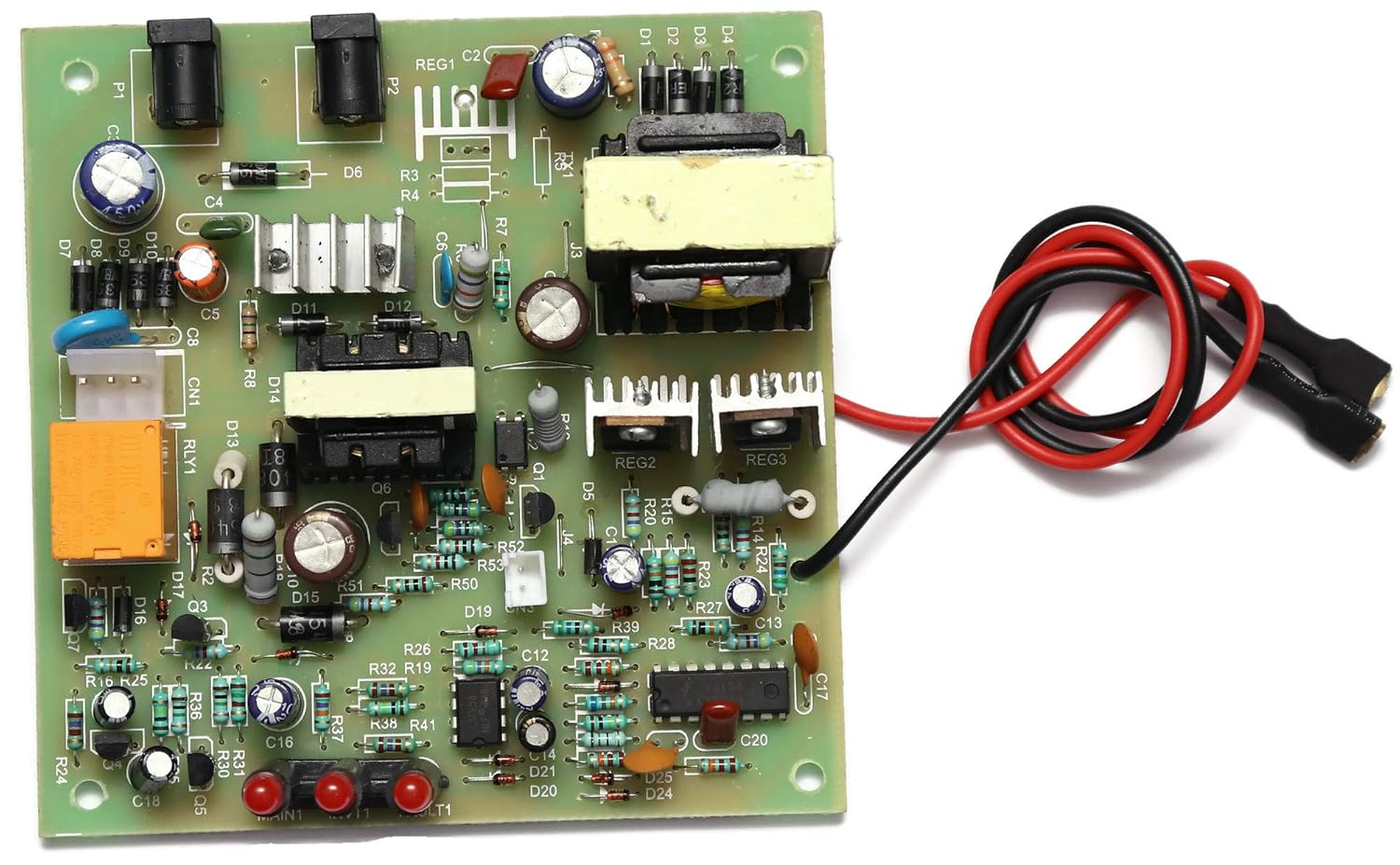
Cfl Or Led Bulb Inverter Ups Circuit Board 45watt With Inbuilt Charger Circuit For Upto 7a Battery Amazon In Industrial Scientific

Scematic Machine Inside 45w Cfl Inverter Circuit Diagram

Pin On Circuit Design
Inverter Circuit Page 2 Power Supply Circuits Next Gr

100w inverter 12vdc to 220vac 3 cfl ups inverter circuit diagram.
3 cfl ups inverter circuit diagram.

50 Va 3 Cfl Inverter Card Transformer Based At Rs 250 Piece Inverter Card Id 4912434648
Shows The Complete Circuit Diagram Of The Pwm Inverter Circuit Ic 3 Download Scientific Diagram
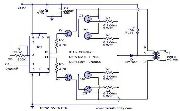
100 Watt Inverter Circuit Diagram Parts List Design Tips
Inverter Circuit Diagram

Icon 50 Va 3 Cfl Inverter Smps Solar Card Rs 290 Piece Lzen Electronics India Id 4907706912
Index 12 Circuit Diagram Seekic Com

Cfl Inverter Internal Wiring Youtube

1000w Power Inverter Circuit Diagram This Is The Power Inverter Circuit Based Mosfet Rfp50n06 The Inverte Power Inverters Circuit Diagram Electronics Circuit

12 24v Sg3524 High Power Inverter Driver Board Square Wave Output Frequency Adjustment 2 Power Inverters Electronic Circuit Projects Electrical Circuit Diagram

If You Are Looking For A Compact Transformerless Ferrite Core Inverter Circuit With Maximum Features This Post Circuit Diagram Circuit Projects Circuit Design
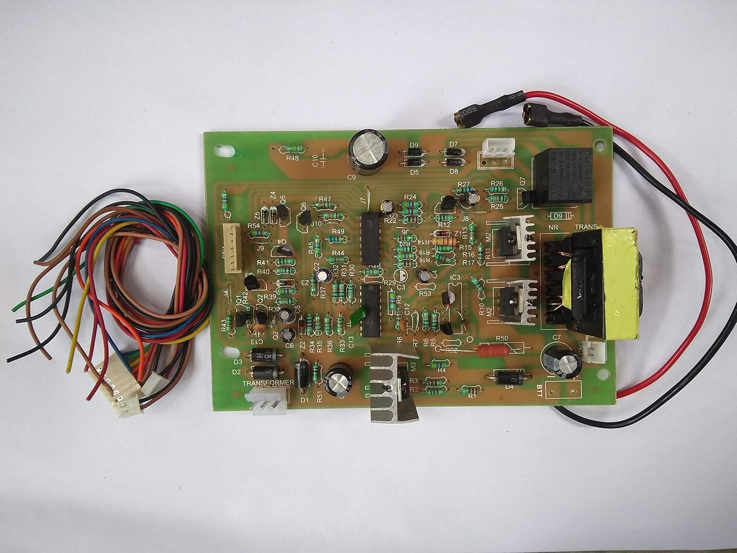
Amazon In Buy Rashri Multicolor Mother Board Pcb Of Cfl Inverter 45 Watt Used For Wi Fi Mobile Charger Dc Fan Online At Low Prices In India Rashri Reviews

Cfl Inverter Kits Digital Cfl Inverter Kits Manufacturer From Delhi

Led Cfl Inverter Youtube

Diagram Electric Meter Diagram Form Full Version Hd Quality Diagram Form Kywiring2e Giure It
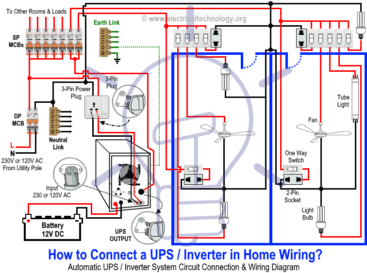
How To Connect Automatic Ups Inverter To The Home Supply System

Pin Di Divers
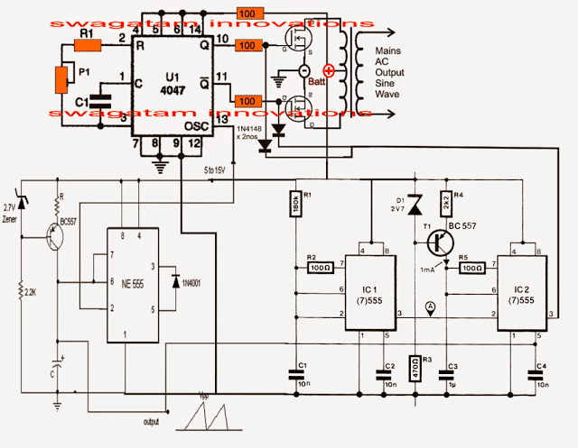
Pure Sine Wave Inverter Circuit Using Ic 4047 Homemade Circuit Projects
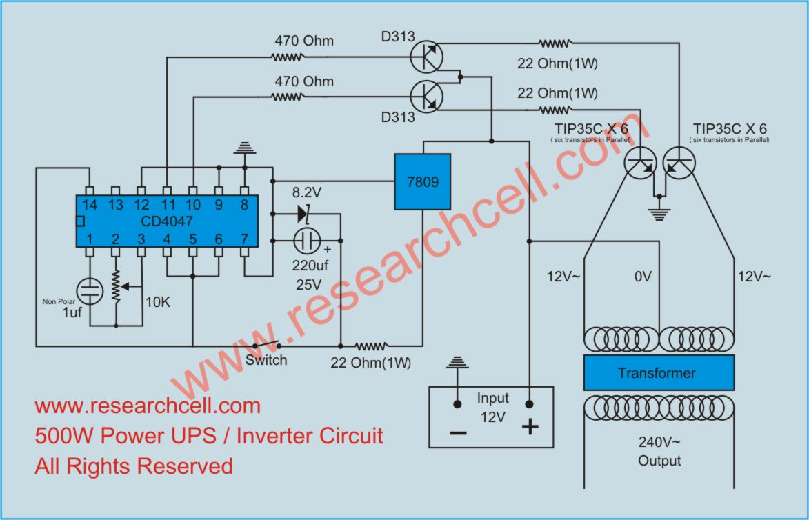
3kw Ups Schematic Wiring Diagram Electronic Circuit Projects Circuit Diagram Electronics Circuit
Https Encrypted Tbn0 Gstatic Com Images Q Tbn And9gcrwudhrrynlrkrxkvxkpqtfskp Fku3gblhtlraifwwacosg14 Usqp Cau

3kw Ups Schematic Wiring Diagram Electronic Circuit Projects Circuit Diagram Electronics Circuit

How An Inverter Functions How To Repair Inverters General Tips Homemade Circuit Projects
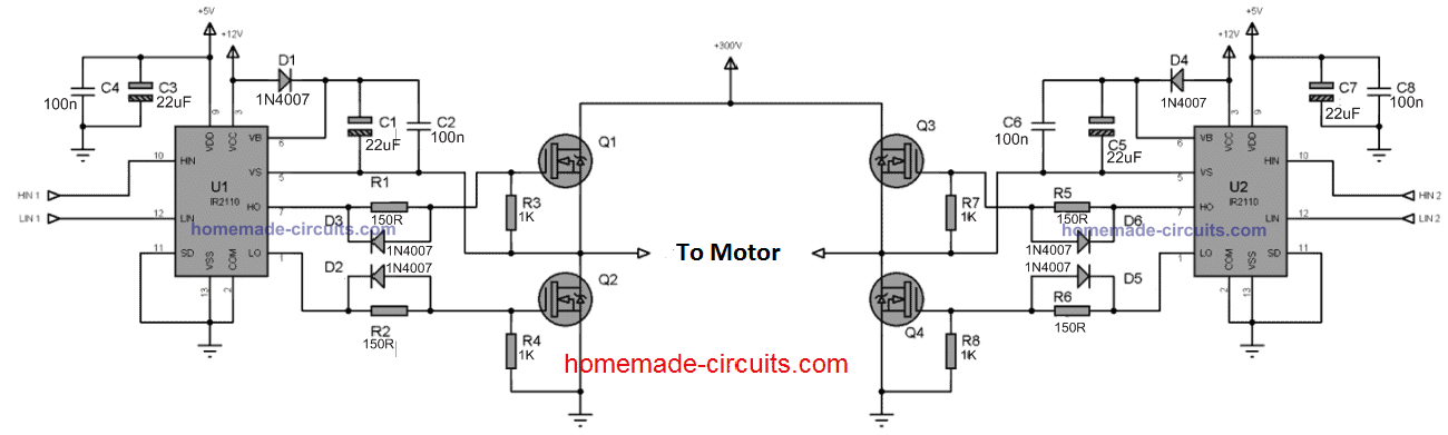
Simplest Full Bridge Inverter Circuit Homemade Circuit Projects

Sinewave Ups Using Pic16f72 Free Circuit Download Homemade Circuit Projects Circuit Projects Circuit Diagram Circuit

Pin On Electronics Diy
Source : pinterest.com
